Collected engineering logs, 3D printing experiments, and hardware builds.
3D Printed Vertical Train
One day I was staring at a empty wall, I dreamed of making a 3D printed toy train that can go on the wall. Of course trains can not go vertically as they are not designed for this. So I decided to make a set of small experiments, and I found out it was possible to go on the wall.
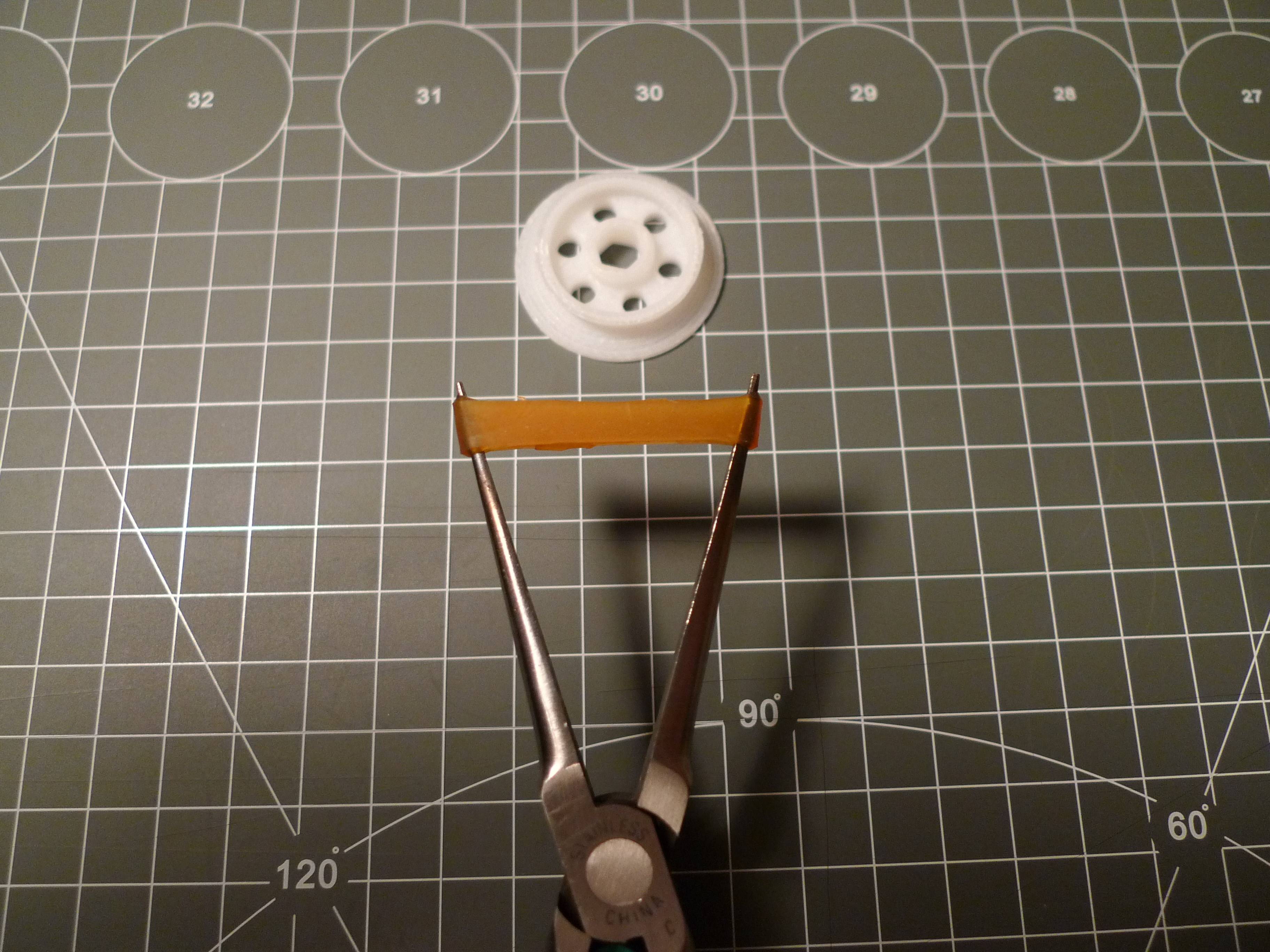
Neodymium magnets provide the attraction of the train to the base. I immediately realize the magnets would not be enough. For the train to go vertically, first we needed motors that can overcome gravity, and the wheels had to have enough friction and grip to hold the train in position. To increase friction the wheels have a special conical shape, and the wheel is coated with slingshot rubber cut in 1 cm pieces, and put on the wheel using pliers.
This is the second version of my “Wall Train”.
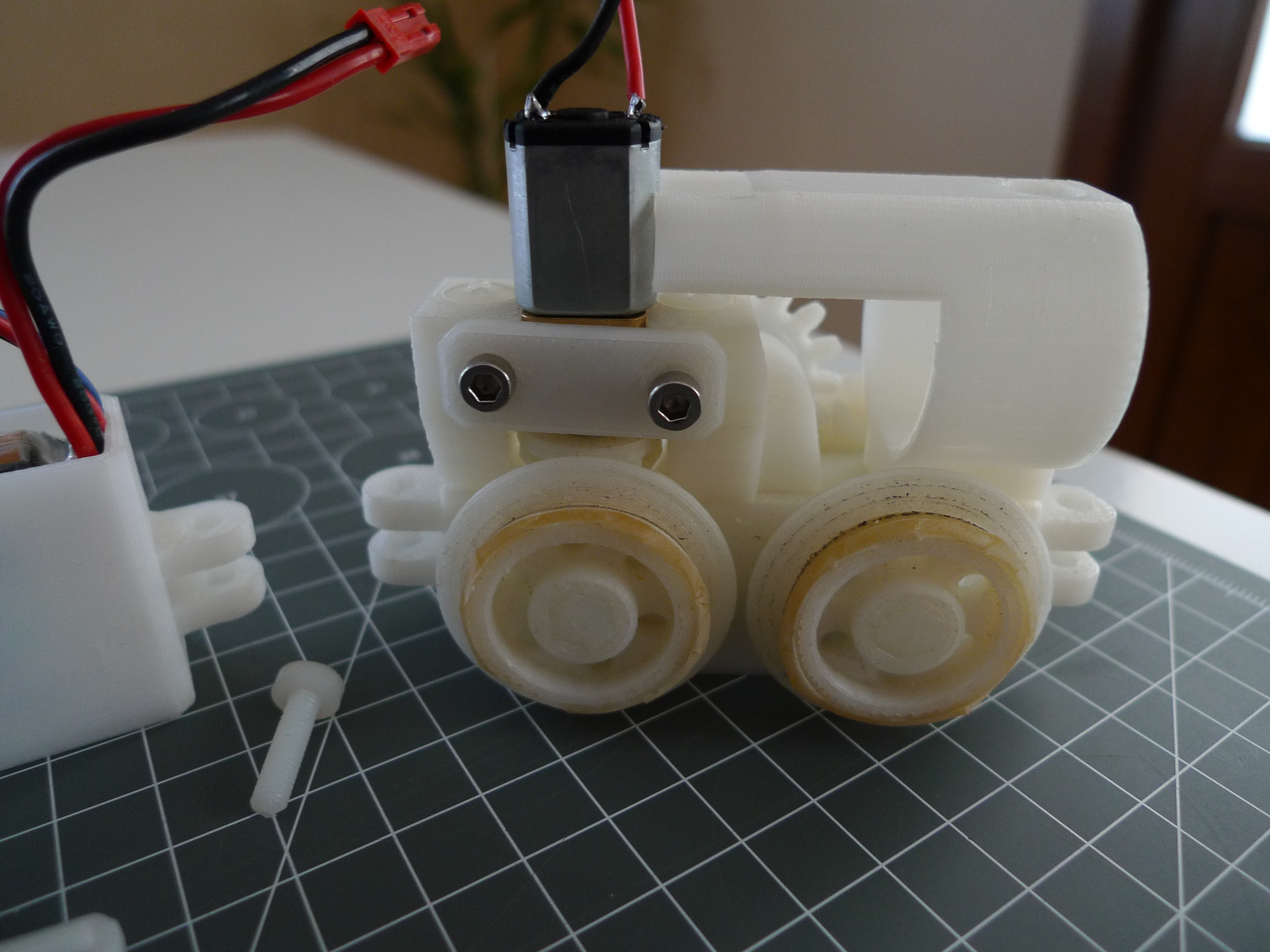
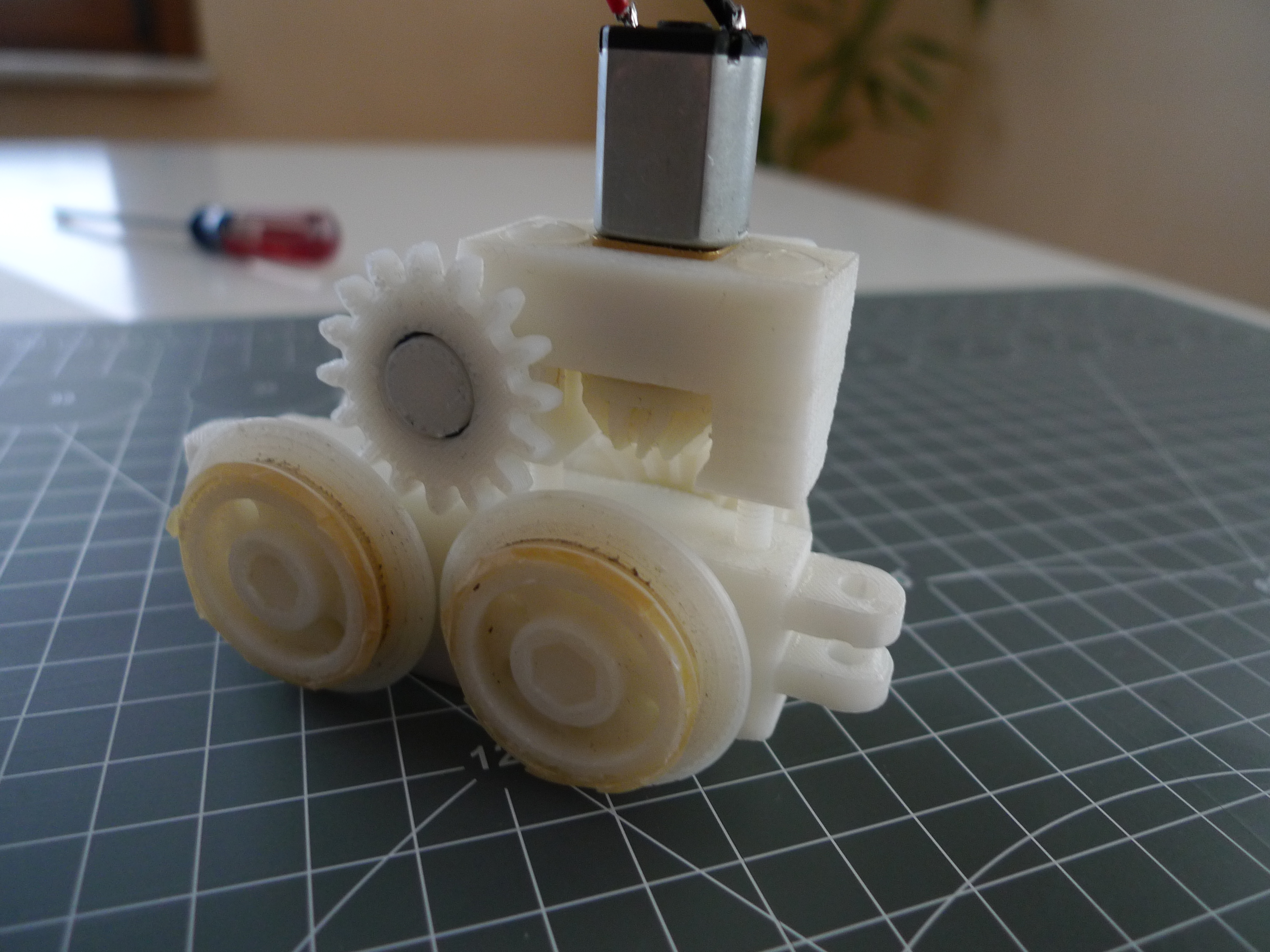
First version had four motors. This version uses only one motor. The locomotive is four wheel drive.
One micro gear motor is used to drive a set of 3D printed gears, that move all four wheels, and the motor has to provide enough power to overcome gravity.
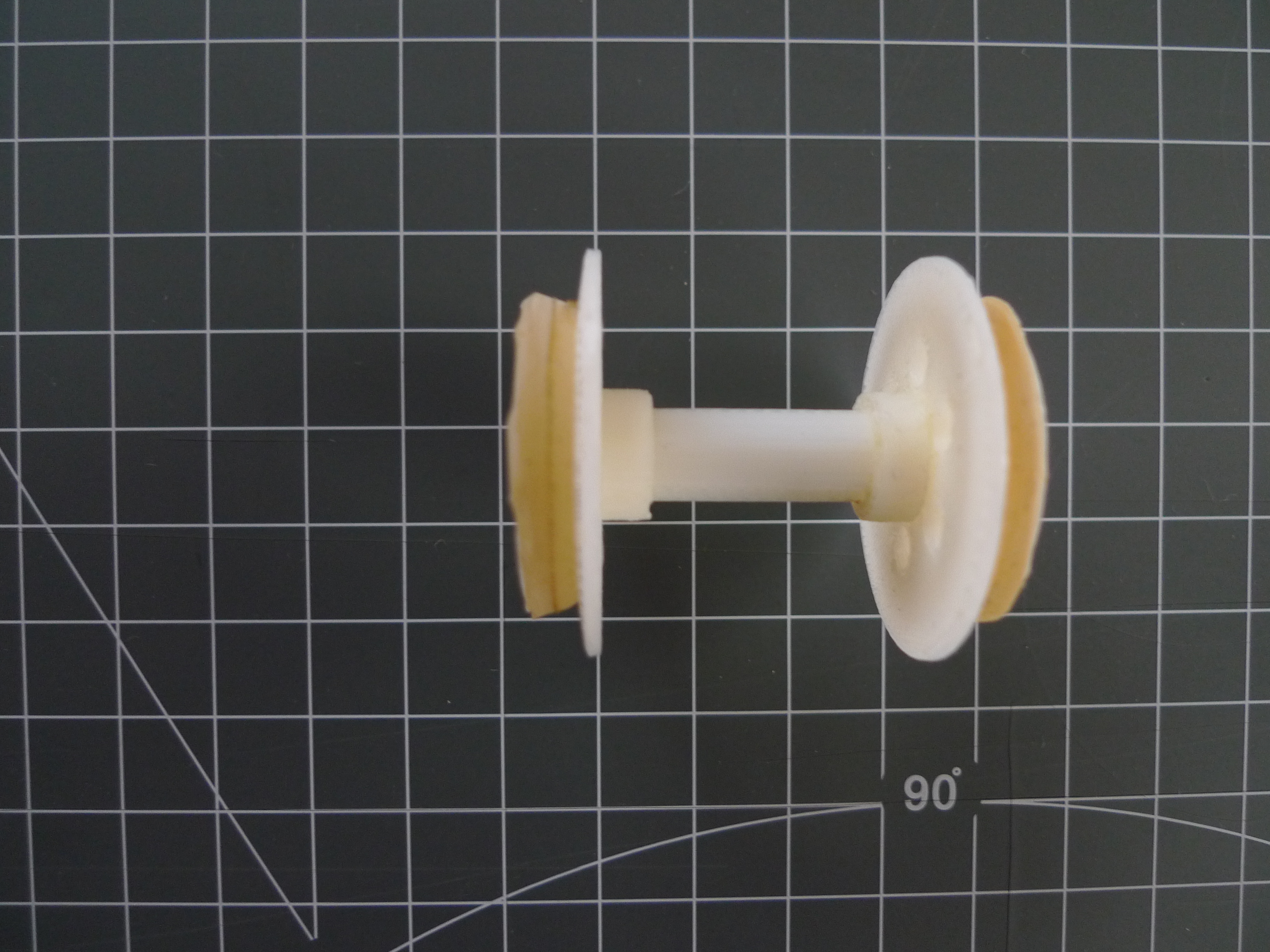
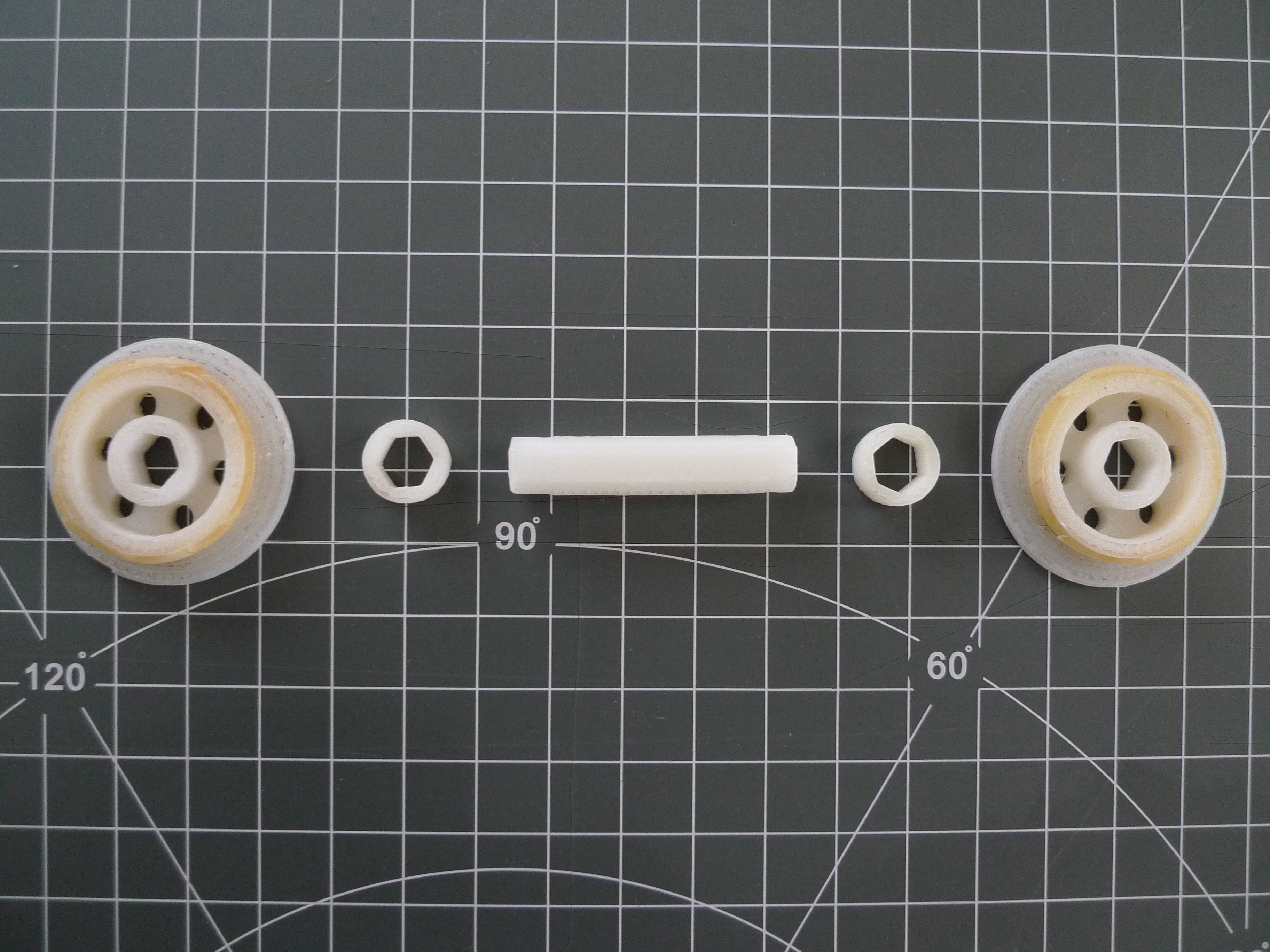
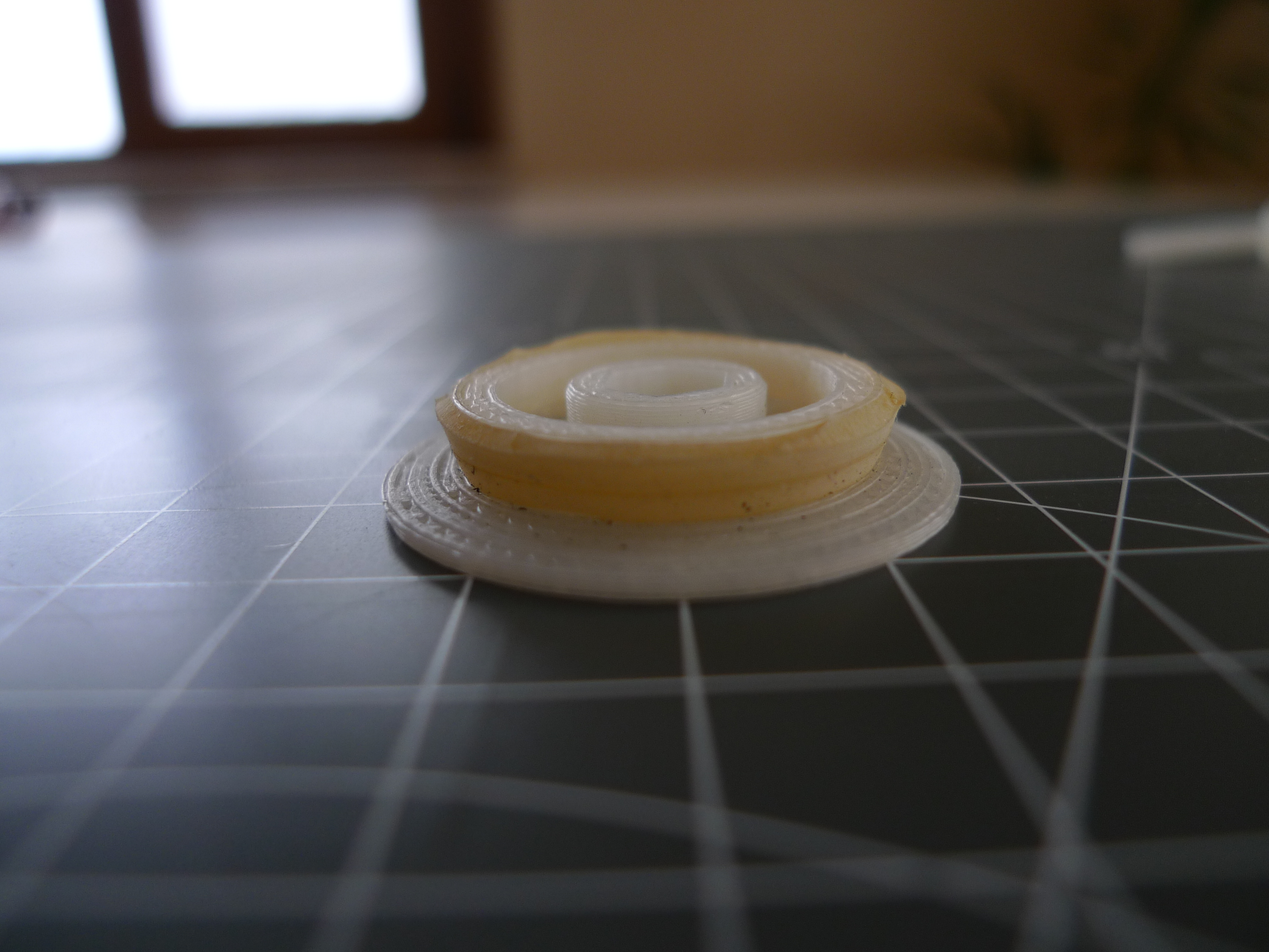
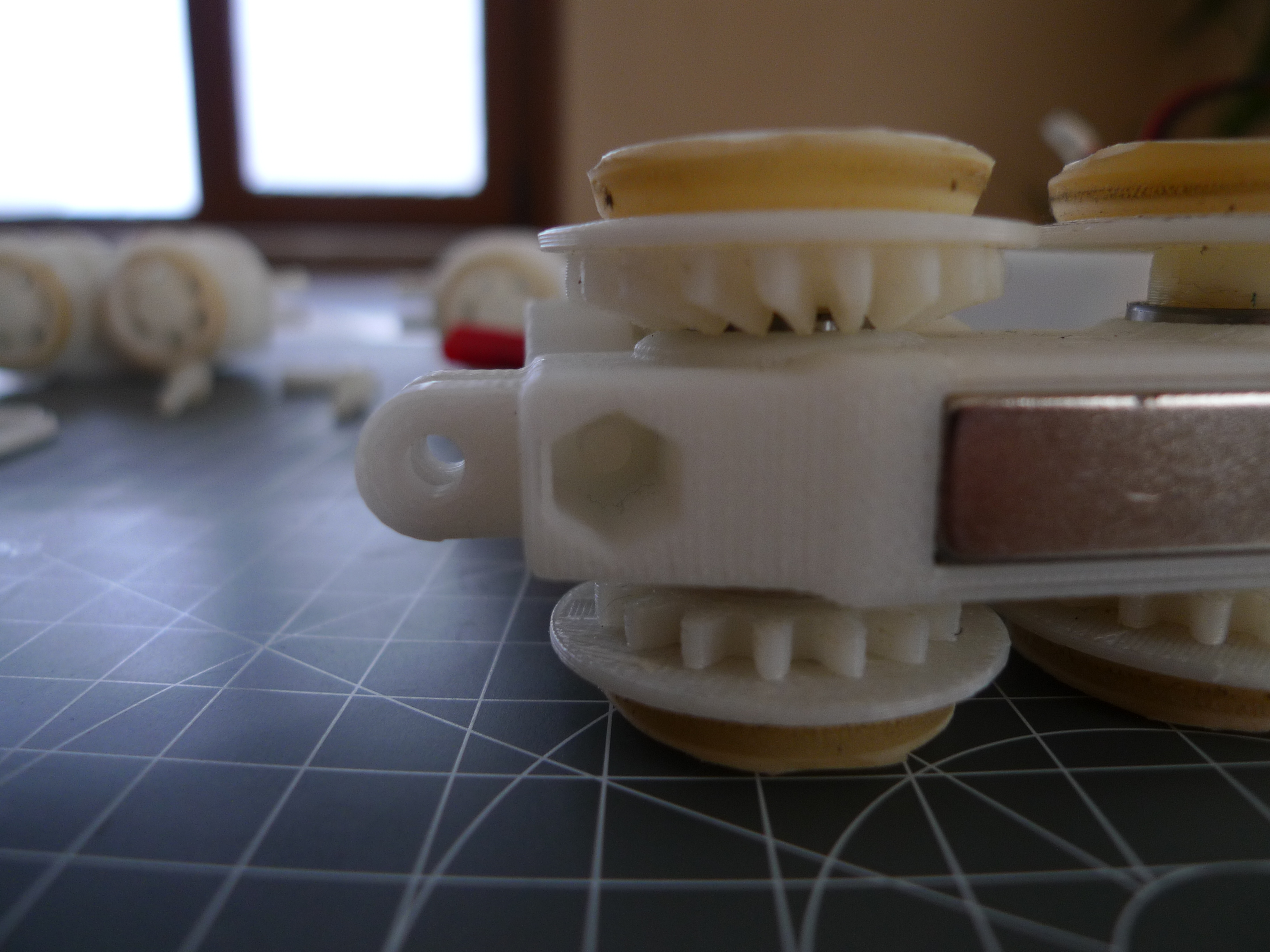
The wheels are designed to maximize friction and grip, and this is accomplished by their grooved shape and rubber coating. Below are 3 photographs that illustrate the wheel system.
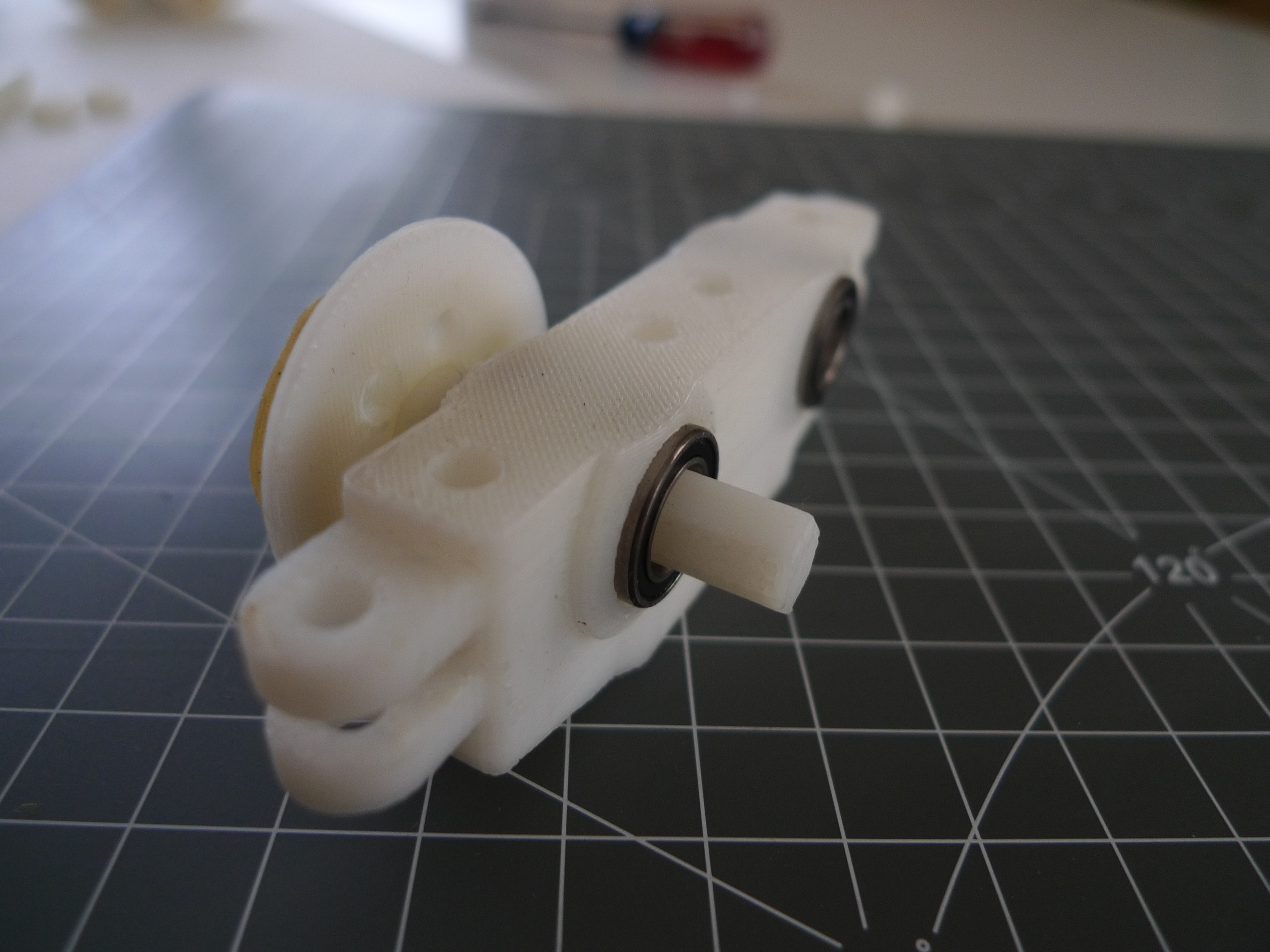
The axes are hexagonal, that fit the wheels tightly. The washers hold the system in place, and washers are also bearing fits, i.e. they roll inside the bearings.
Cross section of the wheel. Notice the reverse conical shape.
The train is magnetically attracted to the base plate by magnets. The green base tracks are made of 1.5 mm steel, cut with a laser cutter and painted with spray paint. The rail tracks are just made out of plastic, and glued on top of steel cut parts.
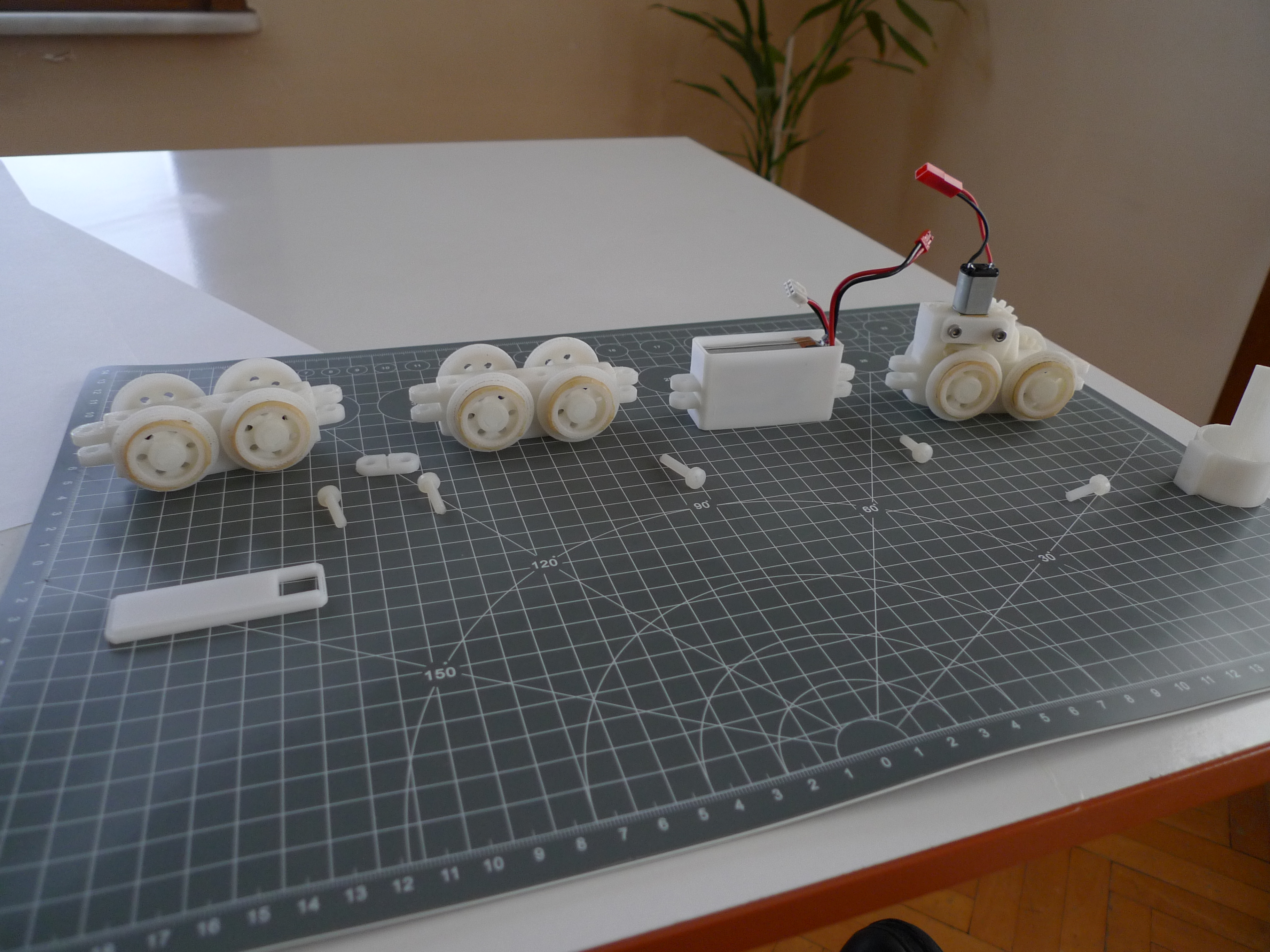
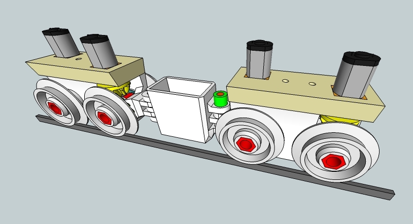
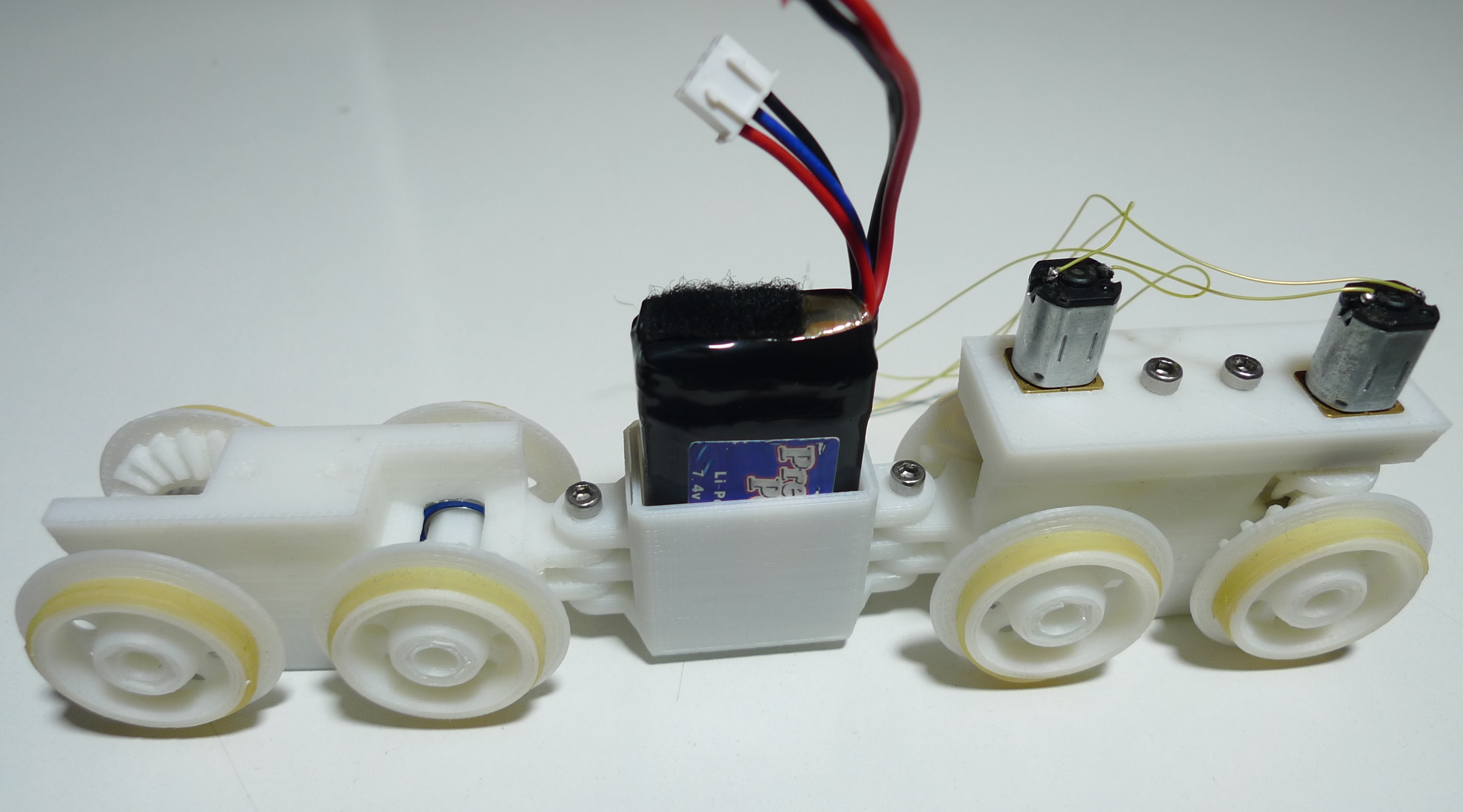
Here is the whole assembly. Two vagons, that dont have motors, a battery carriage, and the locomotive.
This is how the bearings hold the axes. A wagon is also convertible to a locomotive, they use the same base.
The mounted locomotive with the top part. Gear-motor drives back wheel with bevel gearing mechanism. The motion is conducted to the opposite wheel, which then turns the front axis with the middle flat gear. I had to butcher some toy trains to get this working. This way, all the wheels turn, like in 4WD. Of course I realize the whole system is not really efficient, but that was not the design objective.
So there are few more photos in my flickr roll with few more explanations:
An experiment gone wrong
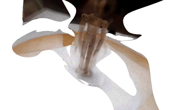
An experiment gone wrong: while trying to reconstruct photos into a 3D model, figured out the algorithm was flawed, as well as the pictures I took. However it did produce some interesting results.
The object scanned at different angels was a wooden puppet.
Which resulted with a human like mest, but not really.
The Vertical Wall Train
Of course trains are not built to go vertically, because they are not designed for this, but I wanted to see the building capacity of my 3D printer, so after making few tests, I decided it was possible for a train to go vertically.
First I put some magnets under carriages, but I quickly found out magnets alone would not be enough. For the train to go vertically, first motors must be powerful enough to overcome gravity, and the wheels needed much more traction than normal.
For this, I made special wheels that are conical in cross section, and covered with slingshot rubber. So I sliced the slingshot rubber into rings, and then snapped them over these conical wheels. Also each wheel is driven by an independent motor.
I also made a battery carriage for the middle part. There are ball bearings inside the carriages, that hold the axes, which snaps to the wheels.
The hardest part was to design the gears. The stock gears I found on the internet were not sufficient, as I made few changes in the linkages.
The first carriage has the gearmotor part removed for clarity.
This was the first working prototype. It did work as planned, but in the process I have learned alot about the whole process. So, I designed a new version, that worked with only one motor, and was easier to build, which I will explain in more detail in my next blog post.
All need to document what they do.
A distance measuring robot prototype
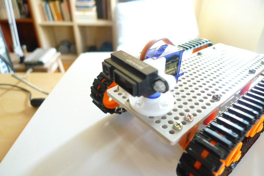
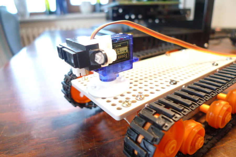
A Tamiya bot chassis is fitted with a servo and a sharp IR distance meter. The white parts were printed with a 3D printer, which are the base plate and the servo-sensor mount.
Problem with these kind of sensors are they tend to miss small targets such as the legs of a chair. Also they are sensitive to reflective conditions of the surfaces.
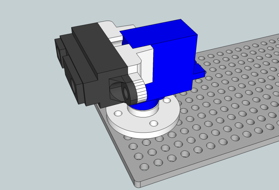
Above is the sketch-up drawing for the whole thing. Luckily we have better sensors these years. For anyone making a similar project I would recommend to go with Ultrasonic sensors instead.
Plant Life Support System
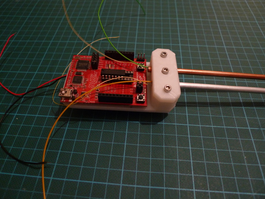
Made a probe to measure Ph, Humidity, Temperature and light conditions. The whole system works on a MSP430 based MCU. Each 10 minutes the MCU wakes up makes a couple thousands of measurements, calculating average values and storing them EEPROM, which then can be dumped to a computer to generate graphs.
Here is one little interesting thing about sensors: No matter how cheap and error-full your sensors are, if you take thousands of measurements and average them, you will get the correct values, like as if you have an expensive sensor that is error free, of course with in certain limits.
Above is the bamboo plant I monitored for some time. One problem with the system was power consumption of the EEPROM write cycles. I optimized the whole system for low power operation, but to write to EEPROM requires a lot of power draining the batteries.
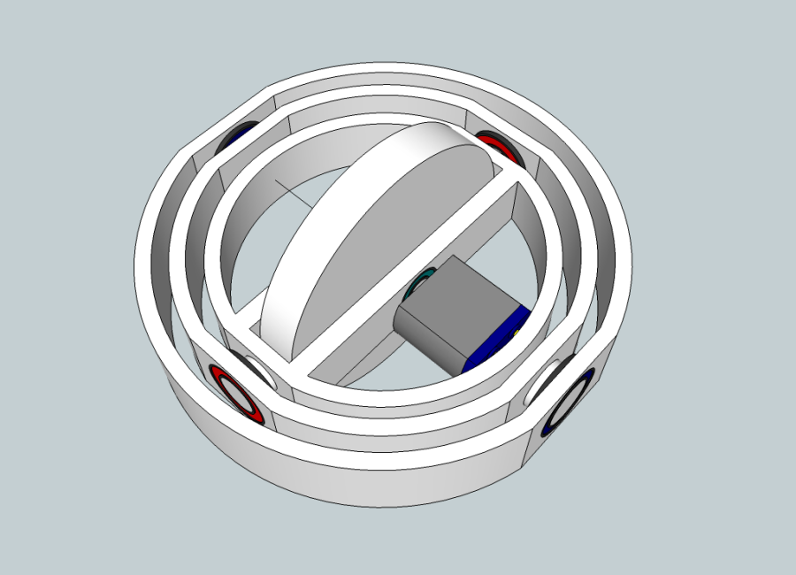
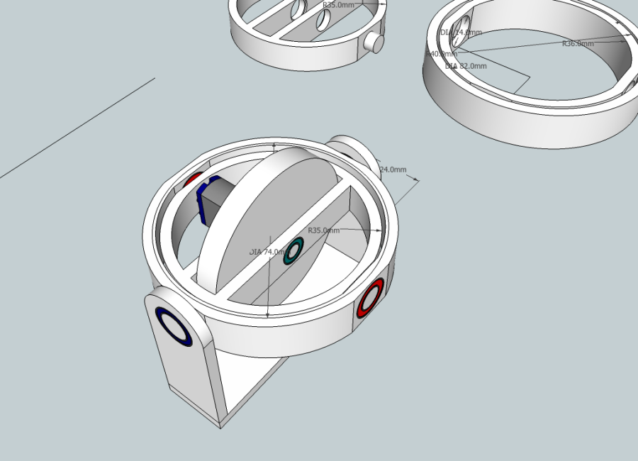
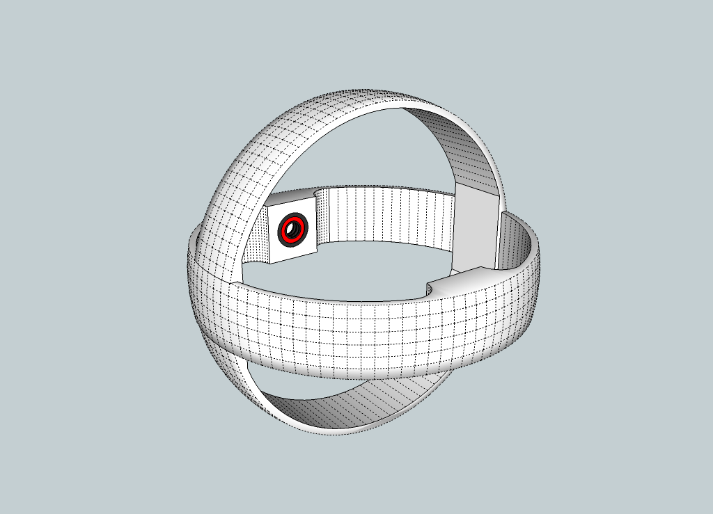
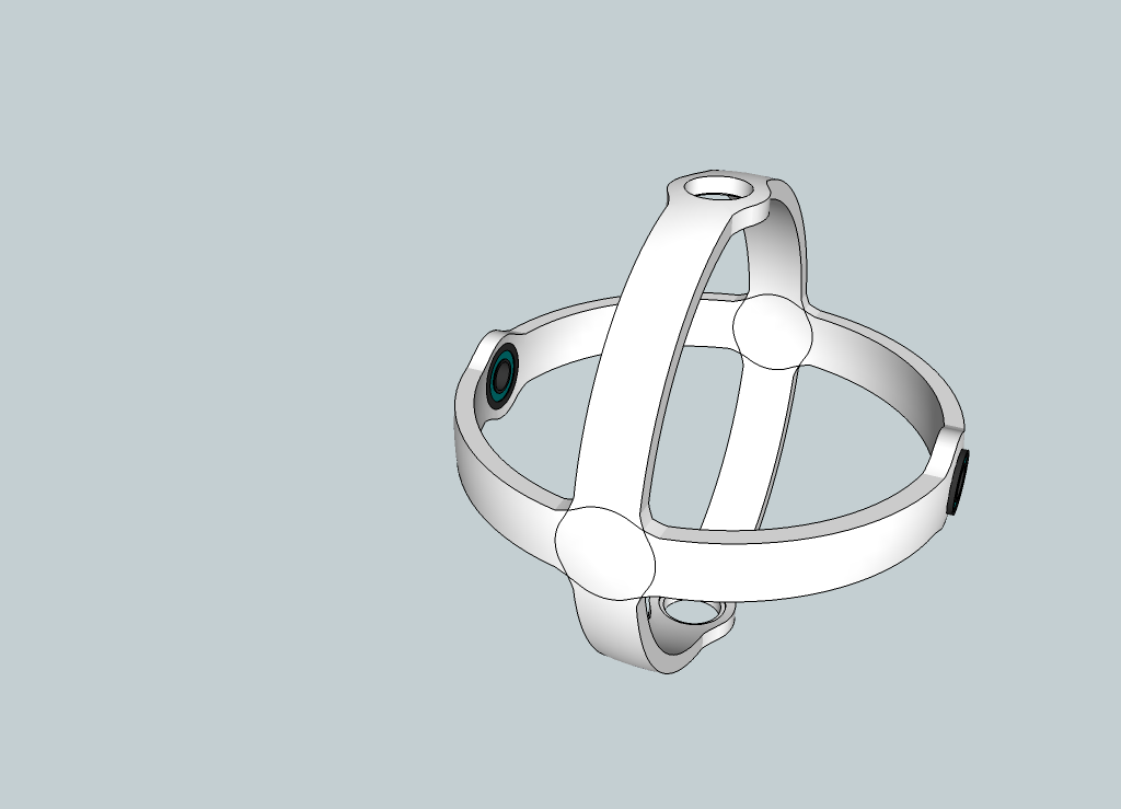
Sketches of Gyroscopes
So I wanted to make a gyro with my 3D printer. Never finished it but made some progress on design, and learned sketchup in progress.
This above is the first prototype.
I played with it a little bit more but unsatisfied with results, I scrapped it and made a new one:
This is how it should look like. Notice the round curves, which enables better clearance between rings. However never finished the project.
A lighter version above. Notice the ball bearing housings.
And a single slice. I want to make a snap fittings between the rings later on.
DIY air conditioner
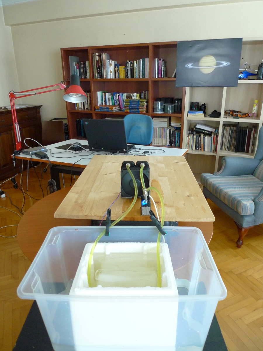
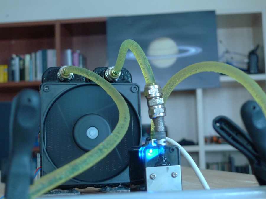
A bucket full of ice, a liquid cooler pump and a radiator is combined to make a home made air conditioner.
Works pretty neatly for couple of hours.
Pictured above is the radiator and liquid cooling pump. The pump circulates water that is kept in the icebucket tru the radiator. Radiator blows room temperature air, cooling the air down, but warming the water. Warm water the goes to the ice bucket.